REQUEST A FREE ESTIMATE!
Conveyor Safe Zone Safety Fence Enclosure Interlock Placement
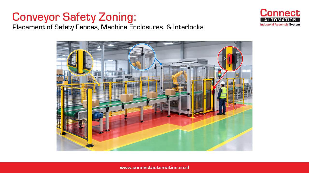
Conveyor Safety Zoning: Placement of Safety Fences, Machine Enclosures, and Interlocks in Production Lines
In industrial production lines, conveyors often operate as part of an integrated system connecting filling, packaging, and material handling processes. While these systems improve production efficiency, combining multiple conveyors with automated machinery also introduces mechanical hazards that must be properly managed.
Belt conveyors have potential nip points around pulleys, modular belt and table top chain conveyors use sprocket-driven mechanisms, and roller conveyors contain rotating components that may create drawing-in, crushing, or entanglement hazards.
Safety challenges become more complex when operators need to interact with conveyors to inspect products, make adjustments, or respond to production interruptions.
For this reason, conveyor safety cannot be achieved simply by installing fences or covers around selected machine components. A more systematic approach is required through conveyor safety zoning, which considers hazardous locations, operator access requirements, and the appropriate placement of safety fences, machine enclosures, and safety interlocks.
Effective safety zoning helps production facilities maintain necessary access while reducing the risk of personnel coming into contact with hazardous moving machinery.
1. Why Is Safety Zoning Important in Conveyor Production Lines?
Safety zoning is an approach to identifying and controlling hazardous areas based on machine characteristics, production layouts, and human interaction with equipment. In a long conveyor system, the level and nature of risk may vary significantly between different sections.
For example, the middle section of a belt conveyor may transport products without requiring direct operator interaction. However, drive and tail pulley areas can contain dangerous nip points if they are accessible. A similar situation occurs when conveyors are connected to packaging machines. Operators may need access to designated product handling areas, while drive mechanisms and hazardous transfer components must remain protected.
Safety zoning helps engineering teams determine:
- Areas that operators may access during normal operation.
- Locations where moving machinery requires guarding.
- Sections that may require safety fences or machine enclosures.
- Access points that may need safety interlocks.
- Safe inspection and maintenance access routes.
In practice, safety zones must be established through a machine risk assessment, rather than simply according to the physical position of equipment.
This approach is consistent with the principles of ISO 12100, which addresses hazard identification, risk assessment, and risk reduction throughout the machine design process.For a broader understanding of machine protection, read our article on the Role of Safety Guarding in Industrial Workplace Safety.
2. Identifying Hazardous Points on Different Conveyor Types
Before determining the placement of safety guarding, the first step is to identify potential hazards associated with each conveyor type. Although conveyors share the primary function of transporting products, their drive mechanisms and mechanical configurations create different hazards.
Belt Conveyors: Nip Points Around Pulleys and Belts
One of the most important hazards associated with belt conveyors is the nip point, particularly where a moving belt approaches and contacts a pulley. These locations may create drawing-in or entanglement hazards if hands, clothing, or other body parts come into contact with the moving mechanism.
Areas requiring evaluation include:
- Drive pulley: The point where the belt approaches the drive pulley.
- Tail pulley: The area where the belt changes direction and enters the return path.
- Return rollers: Belt-to-roller contact points that may create accessible hazards.
- Transfer points: Product transfer locations that may contain gaps or moving mechanisms.
Not every roller or contact point presents the same level of risk. Hazard identification must consider movement direction, accessibility, machine geometry, and the potential consequences of contact. Where hazardous nip points are accessible, fixed guards or localized enclosures may be appropriate to prevent direct contact.
Modular Belt Conveyors: Sprockets and Return Belt Areas
Modular belt conveyors use interlocking plastic modules to form a continuous conveying surface. Many designs use sprockets to drive the modular belt.
Potential hazardous areas include:
- Locations where the modular belt engages with sprockets.
- Drive and return belt sections.
- Transfer points between conveyors.
- Accessible drive mechanisms and moving components.
Risks may increase when operators attempt to remove jammed products or clean accumulated residues near moving components. Guarding design must also consider cleaning and inspection requirements, particularly for modular conveyors used in food processing applications.
However, the need for cleaning access does not justify leaving hazardous moving components exposed during normal operation.
Table Top Chain Conveyors: Sprockets, Chains, and Guides
Table top chain conveyors are widely used to transport bottles, cans, and packaged products through filling and packaging lines. Potential hazards may occur around chain drives, changes in conveyor direction, and locations where moving components approach stationary structures.
Areas requiring evaluation include:
- Drive and return sprockets.
- Chain entry points into the track.
- Contact points between chains and certain guide components.
- Curved sections with potential pinch or trapping points.
- Product transfer areas requiring operator interaction.
For example, when bottles accumulate along a production line, operators may need to intervene to resolve a blockage. If the chain and guide arrangement allows a hand to enter a hazardous pinch point, appropriate guarding or safe intervention methods are necessary.
Guarding should allow required product handling activities without exposing operators to hazardous drive mechanisms.
Roller Conveyors: Roller Gaps and Drive Mechanisms
Roller conveyors consist of multiple rollers arranged along a product transportation path. In gravity roller conveyors, rollers rotate as products move across them or under the influence of gravity. Powered roller conveyors use drive systems to rotate the rollers.
Potential hazards include:
- Gaps between rollers and adjacent components.
- Contact points between moving rollers and transported products.
- Chain, sprocket, or belt-driven roller mechanisms.
- Product transfer and directional change mechanisms.
For powered roller conveyors, guarding assessments should include drive components located beneath or alongside the conveying surface. In addition to mechanical hazards, the movement of transported loads must also be considered.
Heavy cartons moving without adequate control may create impact or crushing hazards at transfer points. Therefore, roller conveyor safety assessments should address both rotating mechanisms and the characteristics of transported products.
3. Establishing Safety Zones Within a Conveyor Layout
Once hazardous points have been identified, the next step is to organize conveyor areas according to access requirements and risk characteristics.
Consider a production line consisting of an infeed conveyor, a table top chain conveyor, a packaging machine, and an outfeed roller conveyor.
For illustration, the layout can be divided into four categories.
Zone A — Normal Operating Areas
These are locations where operators perform routine activities, such as monitoring products, operating machine controls, or collecting products at designated handling points.
Examples include:
- Conveyor control stations.
- Operator positions outside hazardous machine areas.
- Designated product collection points with appropriate protection.
- Walkways surrounding the production line.
An operating zone does not mean that every conveyor component can be safely touched. Even where personnel are permitted to work, accessible hazardous moving components must remain adequately protected.
Zone B — Hazardous Mechanical Areas
These zones contain moving components that may create mechanical hazards.
Examples include:
- Belt conveyor drive pulleys.
- Modular conveyor sprockets.
- Table top chain sprockets.
- Powered roller conveyor drive mechanisms.
- Accessible power transmission components.
Depending on the identified risks and access requirements, protection may involve fixed guards, localized enclosures, or other suitable safeguarding measures. Where components do not require access during normal operation, fixed guarding may be an appropriate solution.
Zone C — Maintenance Access Areas
Maintenance zones are locations where technicians must access components for inspection, adjustment, repair, or replacement.
Examples include:
- Motors and gearboxes.
- Conveyor tensioning systems.
- Drive and return pulleys.
- Chain and sprocket assemblies.
- Roller drive components.
Maintenance areas may be located behind fixed guards or within safety-fenced sections. Access must follow appropriate safety procedures based on the work being performed. For activities involving hazardous unexpected movement, energy sources must be isolated and controlled through lockout/tagout procedures or other applicable hazardous energy control methods.
Zone D — Product Transfer Areas
Transfer zones are locations where products move between conveyors or from conveyors into production machinery. These areas must support product flow while addressing possible pinch, drawing-in, or crushing hazards.
Examples include:
- Transfers between belt and roller conveyors.
- Bottle transfers from table top chains into packaging machines.
- Transfers between modular belt conveyors.
- Machine infeed and outfeed sections.
It is important to note that Zones A through D are illustrative layout categories, not standardized safety zone classifications. These categories may also overlap. A product transfer area, for example, may contain hazardous nip points that require additional safeguarding.
The appropriate protective measures must always be selected according to the machine-specific risk assessment.
Example: Safety Zoning in an Integrated Production Line
Consider the following production arrangement:
Belt Conveyor Infeed → Table Top Chain Conveyor → Packaging Machine → Roller Conveyor Outfeed
An initial safeguarding assessment might identify the following considerations:

This example is not a ready-to-install safety design. Guard positions, safety distances, interlock functions, and other protective measures must be validated against the actual machine configuration. The purpose of the layout is to ensure that all relevant hazards are evaluated when multiple conveyors are integrated into a single production line.
4. Placement of Safety Fences, Machine Enclosures, and Safety Interlocks
After establishing the safety zones, the next step is to select appropriate safeguarding measures. Safety fences, machine enclosures, and safety interlocks are not necessarily required together for every conveyor.
Their selection depends on the size of the hazardous area, access frequency, machine characteristics, and risk assessment results.
When Should Safety Fences Be Used?
Safety fences are commonly used to restrict access to larger hazardous operating areas. For example, an automated packaging line may connect several conveyors with packaging equipment and palletizing systems.
If the integrated area contains hazardous machinery that operators do not need to access during normal operation, perimeter safety fencing may be appropriate. Important considerations include:
- Fence position relative to hazardous moving machinery.
- Fence height and opening dimensions.
- The possibility of reaching through, over, or around the fence.
- Maintenance access gate locations.
- Emergency evacuation routes and personnel access requirements.
The distance between a safety fence and a hazardous component must be determined using appropriate safety distance requirements and risk assessment results, rather than visual estimation. For more information about perimeter guarding, read What Is a Safety Fence? Functions and Benefits for Industrial Areas.
When Should Machine Enclosures Be Used?
Machine enclosures are typically used when protection is concentrated around particular machines or mechanisms. On conveyors, an enclosure may be used to restrict access to drive systems, transfer mechanisms, or other hazardous moving components.
For example, the sprocket and chain mechanisms of a table top conveyor may be protected using localized guarding without installing a perimeter fence along the entire conveyor. This approach allows protection to focus on the identified hazard.
However, enclosure design must consider:
- Prevention of access to moving components.
- Inspection from safe positions.
- Maintenance access requirements.
- Mechanical strength and suitability of guarding materials.
- Potential access through gaps or openings.
For more information, read What Is a Machine Enclosure? Functions, Benefits, and Industrial Applications.
When Are Safety Interlocks Required?
Safety interlocks are used with movable guards when opening or changing the position of a guard must initiate a safety-related control function. For example, an access door on a packaging machine enclosure may be equipped with an interlock that initiates a protective stop or prevents hazardous movement when the door is opened.
However, an interlock does not automatically guarantee that all machine conditions are safe. Several considerations are important :
1. Machine stopping time
If hazardous components continue moving after a stop command, the safeguarding system must prevent personnel from reaching the hazard before the movement has stopped.
In some applications, this may require guard locking, which keeps the guard closed until the hazardous condition has ended.
2. Prevention of unexpected restart
Closing an interlocked door must not, by itself, initiate hazardous movement without satisfying the relevant safe reset and start requirements.
3. Integration with safety-related control systems
Interlock safety functions must be designed and validated to achieve the required risk reduction. A conventional position sensor does not automatically provide an adequate safety function.
4. Personnel access requirements
Where a person can enter an enclosed machine area completely, additional measures may be necessary to prevent personnel from being trapped inside or exposed to unexpected machine restart.
These measures may include internal release devices, appropriate reset arrangements, and other protections based on the risk assessment. For further discussion, read The Role of Sensors and Interlocks in Effective Safety Guarding.
5. Operator and Maintenance Access: Avoiding Common Guarding Mistakes
One challenge in conveyor safety design is maintaining effective protection without unnecessarily restricting normal operations.
Guarding that makes routine tasks excessively difficult may encourage unsafe practices, including bypassing or removing protective devices.
For this reason, access requirements should be evaluated early in the design process.
Operator Access vs Maintenance Access
Production operators generally require access to monitor products, operate controls, and perform routine handling activities at designated locations.
Maintenance technicians, on the other hand, may need to remove guards or enter restricted areas to inspect and replace components.
These activities require different risk control measures.

During maintenance, pressing a normal stop button or emergency stop is not sufficient to establish hazardous energy isolation. Electrical, mechanical, pneumatic, gravitational, and other stored energy sources must be considered according to the machine configuration.
Common Mistakes in Conveyor Safety Guarding
Several mistakes should be avoided.
1. Installing safety fences too close to hazardous machinery
A fence that appears sufficiently high may still be inadequate if personnel can reach hazardous moving parts through its openings.
2. Guarding the motor but overlooking nip points
On belt conveyors, hazards are not limited to motors and gearboxes. Pulley areas and belt entry points must also be evaluated.
3. Ignoring hazards beneath the conveyor
Return belts, sprockets, and roller drive mechanisms may remain accessible from underneath the conveyor.
4. Providing access doors without appropriate safeguarding
Where a door provides access to hazardous moving machinery, interlocking or other suitable protective measures may be necessary depending on the risk assessment.
5. Treating emergency stops as substitutes for guarding
Emergency stop devices provide a complementary protective measure for emergency situations. They do not replace the need to prevent access to hazardous machinery.
6. Treating interlocks as substitutes for lockout/tagout
Interlocks help control safety-related functions when movable guards are opened. However, maintenance work requiring energy isolation must still follow appropriate hazardous energy control procedures.
7. Designing guards that obstruct maintenance
Guarding that makes component access unnecessarily difficult may lead to uncontrolled removal or unsafe bypassing practices.
Inspection, component replacement, and maintenance requirements should therefore be considered during the initial design.
8. Conveyor Safety Zoning Checklist
Before placing a conveyor system into operation, engineering, HSE, and maintenance teams can use the following checklist as an initial evaluation tool.

This checklist supports an initial review but does not replace a complete machine risk assessment or the required validation of safety-related systems.
Relevant International Safety Standards
Several international standards provide useful technical references for conveyor safety zoning and machine safeguarding.
- ISO 12100 — General principles of machine risk assessment and risk reduction.
- ISO 14120 — General requirements for the design and construction of machine guards.
- ISO 14119:2024 — Principles for the design and selection of interlocking devices associated with guards.
- ISO 13857 — Safety distances to prevent hazardous zones from being reached by upper and lower limbs.
- ISO 13849-1 — Principles for designing safety-related parts of control systems.
The applicable requirements should be determined according to the machinery involved, risk assessment results, and relevant workplace safety regulations.
7. Conclusion: Conveyor Safety Zoning Must Follow Risk and Production Layout
Effective conveyor safety cannot be achieved simply by installing safety fences or machine enclosures without first understanding the hazards present throughout the production line. Different conveyor types introduce different mechanical hazards. Belt conveyors may contain hazardous nip points around pulleys. Modular belt and table top chain conveyors use sprocket-driven mechanisms, while roller conveyors introduce risks associated with rotating components and moving loads.
Through conveyor safety zoning, engineering teams can identify locations requiring protection, establish appropriate operator access, and plan machine guarding more systematically. Safety fences can restrict access to larger hazardous areas, while machine enclosures protect specific mechanisms. Safety interlocks may be incorporated where movable guards require safety-related access control.
However, selecting these protective measures must be based on a risk assessment rather than simply following the physical layout or installing as many safety devices as possible. A well-designed conveyor safety system effectively reduces risks while supporting practical operation, inspection, and maintenance requirements.
A well-designed conveyor safety system effectively reduces risks while supporting practical operation, inspection, and maintenance requirements.
Discuss Your Conveyor and Safety Guarding Requirements with Connect Automation
Connect Automation provides industrial conveyor and safety guarding solutions to support production and material handling applications.
Planning an integrated conveyor and machine safeguarding system requires consideration of production layouts, hazardous moving components, and operator and maintenance access requirements.
Contact the Connect Automation team to discuss conveyor and safety guarding configurations suited to your production needs.
Explore Connect Automation's Industrial Conveyor Solutions
Connect Automation specializes in providing automation solutions, including conveyor systems, to improve efficiency across various industries. The company delivers cutting-edge technology to help organizations automate tasks and optimize workflows. Connect Automation helps businesses reduce manual efforts, boost productivity, and achieve better outcomes. With a customer-focused approach, the company designs tailored solutions to ensure smooth and effective automation transitions for long-term success.
Kawasan Industri Jababeka Tahap 1, Jl. Jababeka II D Blok C14L Cikarang, Indonesia (17530)
(021) 893 5060 Google Maps
Rungkut Industri III, No. 37, Rungkut Menanggal, Kec. Gn. Anyar Surabaya, Indonesia (60293)
(031) 9985 8624 Google Maps